Introduction
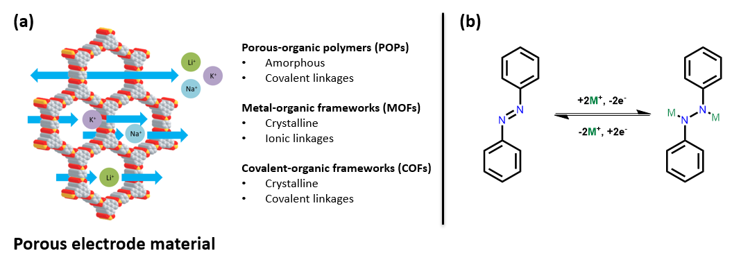
Organic energy storage systems, including batteries and capacitors, have undergone a renaissance in recent years due to a global transition towards an electrically powered world.1 The discovery of highly porous materials such as porous-organic polymers (POPs), metal-organic frameworks2 (MOFs) and covalent-organic frameworks3 (COFs), have allowed for the introduction of a new class of organic redox active energy storage materials. The defining and distinguishing features of each of these materials are shown in Fig. 1A.
Before the advent of these materials, organic redox active functional groups had been limited to molecular species and could not be used in energy storage applications due to dissolution in the electrolyte.4 However, POPs, MOFs, and COFs are all insoluble framework structures and allow organic moieties to be accessible for redox reactions without dissolving.4 Organics make valuable synthetic targets for batteries as the raw components H, C, N, O, S, etc. are much cheaper to source than the metals required to make standard batteries, such as Co. Traditional CoO2 batteries have a pore size only slightly larger than the Li+ ion being used, resulting in the degradation of the material over multiple charge-discharge cycles.5, 6 The large pores within POPs, MOFs and COFs allow for the unimpeded movement of ions through the material thus preventing degradation of the electrode via this mechanism.7,8 The porous nature of these materials and the crystallinity of MOFs and COFs in particular means that essentially all the redox active sites within the electrodes are accessible delivering high specific capacities.4
Additionally, organic redox active functional groups can be used in combination with ions that are cheaper and easier to source than Li+, such as Na+, K+, Mg2+, Zn2+ or Al3+.9-14 The tunability of these molecularly arranged materials allows researchers to design the pore size and geometry to accommodate for the movement of these larger ions. Some common organic redox active species include alkenes, aromatic rings, ketones, imines, azo, or some combination of these functional groups to store energy.15 Between POPs, MOFs and COFs there are more than 1,000 redox active energy storage materials.1
This review focuses on energy storage materials that involve azo bonds (-N=N-) for energy storage. Azo bonds can undergo a reversible two electron redox reaction with a variety of ions (Fig. 1B). Nitrogen has a very low molecular weight which means that materials made with a high density of this material should have a high specific capacity.10,11,16
Azo polymers for energy storage
Azo containing POPs are the easiest to synthesise of the three types of materials discussed. As these polymers are amorphous, it is not a requirement that bond formation be reversible, meaning any number of reactions can be used to make them. Porous polymers have been given many names to describe the same class of amorphous porous polymeric material; polymers of intrinsic microporosity (PIMs), porous-organic polymers (POPs), conjugated microporous polymers (CMPs), covalent organic polymers (COPs) and porous organic frameworks (POFs).17,18 For this review these materials will be referred to as POPs. For POPs there are two strategies through which redox active bonds can be incorporated into the material; firstly, by selecting monomers that contain redox active moieties, or secondly, by forming the redox-active component during polymerisation.
The repeating unit of ALP-8 (Fig. 2A) shows an azo connected polymer which was applied to a sodium-ion battery (SIB).19 The Brunauer-Emmett-Teller (BET) surface area of ALP-8 was a moderate 550 m2/g and the pore size was 1.05 nm, large enough for Na ions to freely move through the material. On the first charge/discharge cycle (see Fig. 2B) ALP-8 had a specific capacity of 315 mAh/g, a value greater than the theoretical capacity which is likely due to the formation of a solid-electrolyte interface (SEI). The SEI is typically formed on the first few charge-discharge cycles. The material stabilises after 2 cycles and plateaus at 170 mAh/g for over 150 cycles with a 96% Coulombic efficiency. The rate capability of ALP-8 was tested at different current densities (Fig. 2C) and the material shows a capacity of 42 mAh/g at 40 C, before recovering to 170 mAh/g at 0.3 C. This is a very high current density to recover from and makes this material one of the highest performing in terms of rate capability among all organic SIBs. Additionally, using Na+, the material is comparable with CoO2 batteries in terms of capacity (~165 mAh/g).20
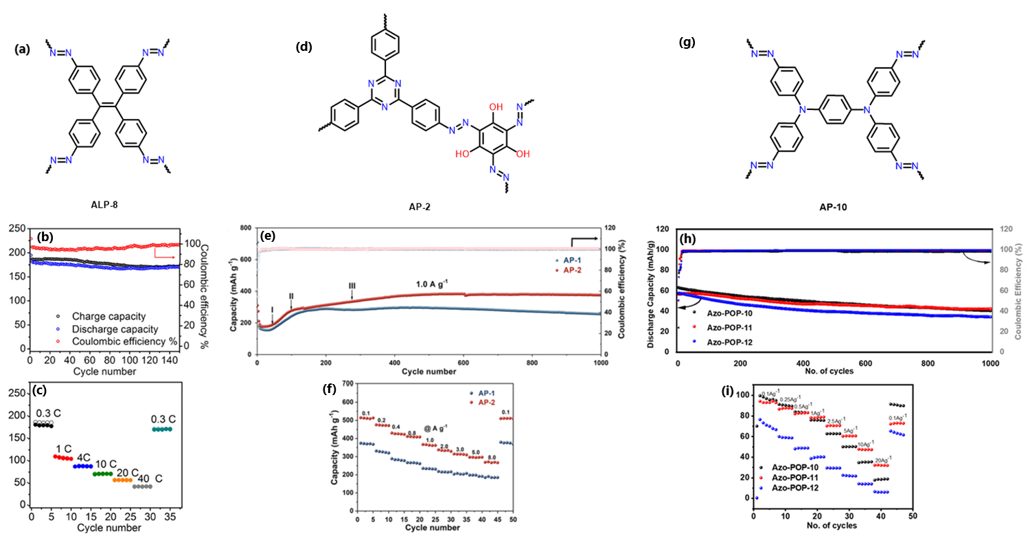
Another azo-containing polymer used as a SIB is AP-2, with the repeating monomer for this material shown in Fig. 2D.21 The BET surface area was 407 m2/g and the pore size was ~1.5 nm. AP-2 showed good cyclability with a maintained capacity of 376 mAh/g after 100 cycles at 1.0 A/g (Fig. 2E). The rate capability was tested by increasing the current density to 8.0 A/g, where AP-2 had a capacity of 273 mAh/g. Once the current density was reduced the capacity recovered to 512 mAh/g at a current density of 0.1 A/g (Fig. 2F). AP-2 has a composite redox site that is composed not only of azo bonds, but of hydroxyl groups and triazine rings as well. This combination of redox active sites may be partially responsible for the increased capacity as well as the reduced sterics required for Na+ to reach the active sites. Overall, this material shows good cyclability and high capacity, especially for a polymeric energy storage system.
AP-10 is tris-phenylamine based 4-connecting POP with azo bonds and aromatic rings for redox active sites (Fig. 2G).22 This material achieved a high percentage of its specific capacity at ~78 mAh/g at 1.0 A/g current density as a lithium-ion battery (LIB) (Fig. 2H). The specific capacity is relatively low since the design of the material does not contain many redox active sites. Even though the capacity for this material is not particularly high, the cyclability of the material is quite good, retaining 87% of its capacity over 1000 cycles (Fig. 2I). AP-10 also has a good capacity retention of 35% at 20 A/g, being able to recover fully after this high current density. Overall, this material shows only moderate capacity but excellent cyclability and good capacity retention. The authors believe the material acts so well at higher current densities due to reactions occurring on the outside of the material causing it to act as a capacitor. AP-10 may be acting as a poor electrode due to its out of plane rings and lack of π-bond conjugation through the tertiary amine.
While these azo-polymers are clearly applicable as energy storage systems for SIBs their application as LIBs is lacking. As anodes in SIBs, they can show good rate capabilities (ALP-8) and show very impressive recoverable capacities like with AP-10. Azo-POPs clearly have the potential to become cheap and effective energy storage systems. The lack of azo-POPs used in literature as anode materials is quite striking given the high performance they have shown.
Azo MOFs for energy storage
MOFs are defined as organic-inorganic hybrid crystalline porous materials. The usual structure for a MOF is a series of metal-oxide nodes connected via an ionic bond to an organic moiety. Typically, the organic molecule used has a terminal carboxylic acid although other coordinating groups can be used as well. MOFs are assembled via a reversible reaction to give the material its regular crystalline structure. Shockingly, given the reasonable performance of azo-containing MOFs, there are currently only four examples of these materials applied to energy storage systems.
Azo-containing MOFs, Cu-MOF and Ni-MOF are composed from 4-connecting 3,3’,5,5’-azobenzenetetracarboxylic acid, with the linker shown in Fig. 3A, using Cu(NO3)2 and Ni(NO3)2 respectively. Both MOFs show excellent crystallinity with an nbo topology for Cu-MOF (Fig. 3B) and an fcu topology for Ni-MOF (Fig. 3C). The azo-MOFs were straightforward to synthesise with unit cells comparable to previously reported syntheses.23,24 Both MOFs show high BET surface areas of 1691 m2/g for Cu-MOF and 1852 m2/g for Ni-MOF with pore widths around 5 nm for both materials. These high surface areas indicate a high degree of order within each MOF. Both materials were tested as LIBs and SIBs.
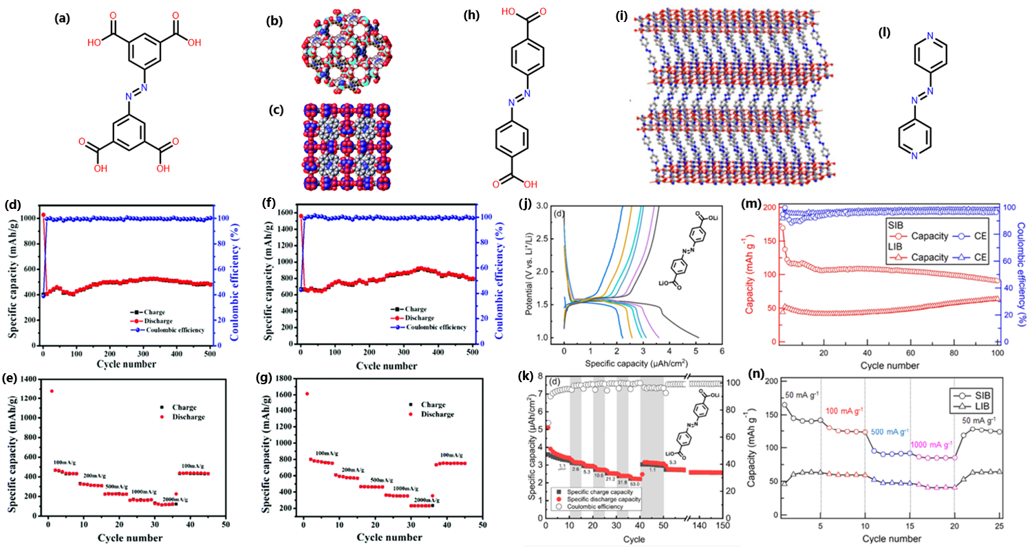
Cu-MOF has shown good performance as an anode material and exhibited an initial discharge capacity of 1027.7 mAh/g and initial charge capacity of 400.8 mAh/g as a SIB (Fig. 3D).25 The irreversible capacity observed is attributed to electrolyte decomposition and the formation of the SEI from incomplete conversions during charging-discharging cycles. From the second cycle, Cu-MOF shows a stable reversible capacity of 470 mAh/g for 500 charge-discharge cycles at 100 mA/g. The rate performance was assessed at different current densities up to 2000 mA/g. Under these conditions the material was able to recover its initial capacity after the current density was reduced to 100 mA/g, indicating excellent rate capability (Fig. 3E).
Ni-MOF showed a better performance than Cu-MOF with an initial discharge capacity of 1560.6 mAh/g and a charge capacity of 667.6 mAh/g as a SIB (Fig. 3F).25 Again, the irreversible capacity is attributed to the formation of the SEI. From the second cycle Ni-MOF showed a reversible capacity of ~700 mAh/g with some fluctuations in the charge-discharge cycle reaching as high as ~910 mAh/g. This material showed a better rate capability than Cu-MOF, recovering to 760 mAh/g at a current density of 100 mA/g after being exposed to 7 charge-discharge cycles at 2000 mA/g (Fig. 3G). Both Cu-MOF and Ni-MOF have demonstrated excellent capacity, rate capability and moderate cyclability.
Another azo containing MOF, Li-AZO, is composed of the 4,4’-azobenzenedicarboxylic acid linker (Fig. 3H) and a Li metal layer, shown in Fig. 3I.26 This material shows relatively high performance as an anode in a LIB. Instead of being grown as stand-alone crystals the material was grown as a thin film directly onto a silicon substrate. While the surface area of Li-AZO was not determined in this study the presence of peaks in the XRD was sufficient to convince the researchers that the material was porous. During cyclic voltammetry (CV) scans Li-AZO shows lithiation at 1.48 V, consistent with other azo materials and a reversible capacity of 2.5 µAh/cm2 (Fig. 3J). This material displays the formation of a SEI upon the first cycle but quickly stabilises. The rate capability of this material shows a semi-recoverable capacity of ~3 µAh/cm2 after the current density was brought to 53 µA/cm2 and then reduced to 1.1 µAh/cm2 (Fig. 3K). Overall, this material does not exhibit particularly good performance as an anode with low capacity that fades at higher current densities.
A similar azo-containing MOF CPL-4, was made using a 2-connecting 4,4’-azopyridine linker (Fig. 3L) and a Cu-oxide metal cluster.27 The surface area of this MOF was moderate at only 416 m2/g while the pore volume was 0.2334 cm3/g, large enough to host Li+ and Na+ ions. Using both Li+ and Na+ allows us to directly compare these alkali metals in the system. The CV curves of CPL-4 shows that Na+ was a higher performing counter ion for this system with little degradation over the course of 10 scans. When CPL-4 used Li+, the stability was similar to Na+ but the capacity dropped significantly from ~110 mAh/g at 50 cycles (SIB) to ~45 mAh/g at 50 cycles (LIB) (Fig. 3M). The rate performance of both ions was tested and showed that for both Li+ and Na+ the material was stable up to 1000 mA/g and retained its initial capacity when the current density was reduced to 50 mA/g (Fig. 3N). A kinetic analysis of both Li+ and Na+ in CPL-4 was performed using CV scans at different speeds and indicated CPL-4 had greater Na+ insertion compared to Li+. Na+ was inserting and de-inserting more deeply into the material while Li+ was only reacting with the surface. This material shows only moderate capacity and poor cyclability, although it does demonstrate that Na+ (or other ions) may perform better than Li+ in these complex organic systems.
The azo MOFs discussed cover most of the energy storage azo-containing MOFs that have been published. Overall, this area of organic energy storage seems to be severely under-researched given some of the excellent results that have been found (Ni-MOF). Very few azo MOFs have been tested as electrodes in an energy storage system. It seems likely that higher performance can be achieved through optimising the number of azo bonds that can be inserted into the framework (per unit mass) and adjusting the metal-oxide linkers to those with reduction potentials outside of the redox window of the azo bond. Azo-MOFs also perform better with Na+ compared to Li+ which is more cost-effective to manufacture, should this material be adopted on a large-scale.
Azo COFs for energy storage
Covalent-organic frameworks (COFs) are a class of material defined by their permanently porous structure, long-range order, and covalently bound monomers. These materials are excellent candidates for electrodes as their porous nature and crystallinity allows for free movement of ions through the material. The covalent linkages of COFs also theoretically make them more stable than MOFs, which would directly affect cyclability of these materials, improving their longevity.
Tp-Azo-COF is composed of 4,4’-azodianiline and 1,3,5-phloroglucinol components which form imine linkages via condensation, the repeating unit is shown in Fig. 4A.28 Tp-Azo-COF contains three distinct redox active moieties: azo, imine and hydroxyl. This COF displays a moderate surface area of 632 m2/g and a pore diameter of ~2.6 nm. Tp-Azo-COF shows reasonable crystallinity with simulated peaks matching well with experimental XRD. This material shows a first discharge capacity of 802 mAh/g which quickly drops to 306 mAh/g after ten cycles at 1 A/g current density. The loss of capacity is attributable to the formation of the SEI. Tp-Azo-COF displays an impressive stable capacity of 306 mAh/g at 1 A/g after 3000 cycles using Li+ (Fig. 4B). During the rate performance testing, after a high current density of 2.4 A/g was observed, the capacity would return to 530 mAh/g once the current density was dropped to 0.1 A/g (Fig. 4C). These results indicate close a to 100% capacity retention and nearly 100% Coulombic efficiency. However, the capacity of Tp-Azo-COF is not due solely to the azo components. Raman spectroscopy of the charged and discharged battery cells shows that the ketone is also binding to Li+ in this system. Tp-Azo-COF showed impressive capacity and rate capability regardless of its moderate porosity.
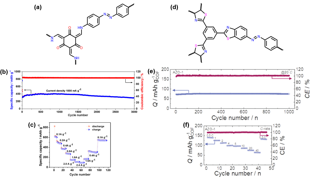
The COF AZO-1 was synthesised with 4,4’azodianinline and 1,3,5-triformylbenzene via an imine condensation, then post synthetically modified the imine linkages to form a thiazole ring, with the repeating unit shown in Fig. 4D. This COF showed a moderate internal surface area of 649 m2/g and a pore diameter of 2.8 nm. AZO-1 has a reasonable reversible capacity of 120 mAh/g after 100 cycles using Li+ (Fig. 4E).29 Interestingly, the material did not show a significant drop in capacity during the first several charge-discharge cycles associated with the formation of the SEI. Rate capability testing showed that AZO-1 was stable up to a current density of 40 mA/g and would recover to its initial capacity of 120 mAh/g at 1 A/g as shown in Fig. 4F. The capacity of AZO-1 was only moderate, this is likely due to the moderate surface area of the material reducing the number of accessible redox sites within AZO-1. This material did perform well when rate tested but this may be due to reactions occurring on the surface of the material making it act as a capacitor.
Very few azo-containing COFs have been applied as energy storage devices but those that have been used as electrodes have shown good capacity, rate capability and stability despite possessing a moderate surface area. Despite the difficulty of synthesising COFs, the materials do appear to have promise as versatile high-capacity energy storage systems.
Conclusions
Azo-containing porous materials are a promising avenue to explore as energy storage systems. There are examples of POPs, MOFs and COFs having all shown capacities greater than the current standard CoO2 batteries and can last for many thousands of cycles. Additionally, azo-containing porous materials have demonstrated charging capabilities with a variety of ions and therefore a greater potential range of applications. Rate capability testing indicates that azo-containing porous materials can act as batteries and capacitors, a desirable combination allowing for large amounts of energy storage and fast power generation. Further study and optimisation of these materials will likely yield even higher performing azo-containing porous materials. Considering the performance of the materials discussed in this review, MOFs are currently the most promising avenue to explore for azo-containing energy storage systems.
References
- Wu, L.; Li, Y.; Fu, Z.; Su, B.-L. National Science Review 2020, 7 (11), 1667-1701.
- Yaghi, O. M.; Richardson, D.; Li, G.; Davis, C.; Groy, T. MRS Online Proceedings Library (OPL) 1994, 371, 15.
- Cote, A. P.; Benin, A. I.; Ockwig, N. W.; O'Keeffe, M.; Matzger, A. J.; Yaghi, O. M. Science 2005, 310 (5751), 1166-1170.
- Shimizu, T.; Tanifuji, N.; Yoshikawa, H. Angewandte Chemie International Edition 2022, 61 (36), e202206093.
- Kabir, M.; Demirocak, D. E. International Journal of Energy Research 2017, 41 (14), 1963-1986.
- Edge, J. S.; O’Kane, S.; Prosser, R.; Kirkaldy, N. D.; Patel, A. N.; Hales, A.; Ghosh, A.; Ai, W.; Chen, J.; Yang, J. Physical Chemistry Chemical Physics 2021, 23 (14), 8200-8221.
- Zhu, D.; Xu, G.; Barnes, M.; Li, Y.; Tseng, C. P.; Zhang, Z.; Zhang, J. J.; Zhu, Y.; Khalil, S.; Rahman, M. M. Advanced Functional Materials 2021, 31 (32), 2100505.
- Chen, X.; Sun, W.; Wang, Y. ChemElectroChem 2020, 7 (19), 3905-3926.
- Khayum, A.; Ghosh, M.; Vijayakumar, V.; Halder, A.; Nurhuda, M.; Kumar, S.; Addicoat, M.; Kurungot, S.; Banerjee, R. Chemical Science 2019, 10 (38), 8889-8894.
- Liang, Y.; Luo, C.; Wang, F.; Hou, S.; Liou, S. C.; Qing, T.; Li, Q.; Zheng, J.; Cui, C.; Wang, C. Advanced Energy Materials 2019, 9 (2), 1802986.
- Luo, C.; Xu, G. L.; Ji, X.; Hou, S.; Chen, L.; Wang, F.; Jiang, J.; Chen, Z.; Ren, Y.; Amine, K. Angewandte Chemie International Edition 2018, 57 (11), 2879-2883.
- Shi, R.; Liu, L.; Lu, Y.; Wang, C.; Li, Y.; Li, L.; Yan, Z.; Chen, J. Nature Communications 2020, 11 (1), 178.
- Sun, R.; Hou, S.; Luo, C.; Ji, X.; Wang, L.; Mai, L.; Wang, C. Nano Letters 2020, 20 (5), 3880-3888.
- Zhang, Q.; Wei, H.; Wang, L.; Wang, J.; Fan, L.; Ding, H.; Lei, J.; Yu, X.; Lu, B. ACS Applied Materials & Interfaces 2019, 11 (47), 44352-44359.
- Schon, T. B.; McAllister, B. T.; Li, P.-F.; Seferos, D. S. Chemical Society Reviews 2016, 45 (22), 6345-6404.
- Wang, Y.; Yang, Z.; Xia, T.; Pan, G.; Zhang, L.; Chen, H.; Zhang, J. ChemElectroChem 2019, 6 (19), 5080-5085.
- Wang, S.; Li, H.; Huang, H.; Cao, X.; Chen, X.; Cao, D. Chemical Society Reviews 2022, 51 (6), 2031-2080.
- Zhang, Y.; Riduan, S. N. Chemical Society Reviews 2012, 41 (6), 2083-2094.
- Weeraratne, K. S.; Alzharani, A. A.; El-Kaderi, H. M. ACS Applied Materials & Interfaces 2019, 11 (26), 23520-23526.
- Liu, Q.; Su, X.; Lei, D.; Qin, Y.; Wen, J.; Guo, F.; Wu, Y. A.; Rong, Y.; Kou, R.; Xiao, X. Nature Energy 2018, 3 (11), 936-943.
- Shan, Y.; He, Y.; Yang, N.; Zhu, X.; Liu, H.; Jiang, H.; Li, C. Small 2022, 18 (1), 2105927.
- Ahmed, S.; Amin, K.; Younis, M.; Wei, Z.; Huang, M.-H. ACS Applied Energy Materials 2023.
- Wang, X.-S.; Ma, S.; Rauch, K.; Simmons, J. M.; Yuan, D.; Wang, X.; Yildirim, T.; Cole, W. C.; López, J. J.; Meijere, A. D. Chemistry of Materials 2008, 20 (9), 3145-3152.
- Cairns, A. J.; Perman, J. A.; Wojtas, L.; Kravtsov, V. C.; Alkordi, M. H.; Eddaoudi, M.; Zaworotko, M. J. Journal of the American Chemical Society 2008, 130 (5), 1560-1561.
- Zhou, Y.; Wu, M.; Luo, Y.; Pang, B.; Su, X.; Zhou, M.; Han, L. New Journal of Chemistry 2019, 43 (4), 1710-1715.
- Multia, J.; Heiska, J.; Khayyami, A.; Karppinen, M. ACS Applied Materials & Interfaces 2020, 12 (37), 41557-41566.
- Shimizu, T.; Mameuda, T.; Toshima, H.; Akiyoshi, R.; Kamakura, Y.; Wakamatsu, K.; Tanaka, D.; Yoshikawa, H. ACS Applied Energy Materials 2022, 5 (4), 5191-5198.
- Zhao, G.; Zhang, Y.; Gao, Z.; Li, H.; Liu, S.; Cai, S.; Yang, X.; Guo, H.; Sun, X. ACS Energy Letters 2020, 5 (4), 1022-1031.
- Singh, V.; Kim, J.; Kang, B.; Moon, J.; Kim, S.; Kim, W. Y.; Byon, H. R. Advanced Energy Materials 2021, 11 (17), 2003735.