With increasing awareness of the damage traditional methods of chemical synthesis can do to both chemists and the environment around us, chemists need to turn to emerging technologies for better solutions. Flow chemistry has immense potential to enable the transition to safer, greener chemical synthesis. Jie Ma and Zoe E. Wilson take a look.
Green chemistry
Human history is tragically riddled with examples demonstrating the potential of chemicals to cause harm. The indiscriminate use of non-selective pesticides such as dichlorodiphenyltrichloroethane (DDT, 1) endangered biodiversity, exposed in Rachel Carson’s 1962 book “Silent spring”.1 Incorrect disposal of waste containing dioxin (2) produced in chemical manufacture led to the town of Times Beach in Missouri being abandoned in the 1980s2 and horrific examples, such as the methyl isocyanate (3) release in Bhopal, India, in 1984 which killed at least 3,800 people immediately and can be linked to 15,000 – 20,000 premature deaths in the subsequent 20 years, remind us just how badly things can go wrong in chemical synthesis and manufacture (Fig. 1).3

Fig. 1. Chemicals involved in major historic incidents.
While these events, and others, have led to increased regulation and improved safety practices, chemistry is still intrinsically hazardous to both chemists and the environment. Yet chemistry plays an essential role in meeting society’s basic needs of food, clothing, shelter, health, energy and clean air, water and soil. So how do we as chemists meet these requirements without perpetuating the existing problems? Green chemistry (also known as sustainable chemistry) is the solution to this challenge.
Green/sustainable chemistry is defined as "a scientific concept that seeks to improve the efficiency with which natural resources are used to meet human needs for chemical products and services. Sustainable chemistry encompasses the design, manufacture and use of efficient, effective, safe and more environmentally benign chemical products and processes” by the Organisation for Economic Co-operation and Development (OECD).4
Green chemistry originated in the Environmental Protection Agency in the United States of America in the 1990s.5 Paul Anastas and John Warner’s 12 Principles of Green Chemistry (summarised in Fig. 2), which were published in 1998,6 have been increasingly adopted as a framework for “best practice” for chemical synthesis.7
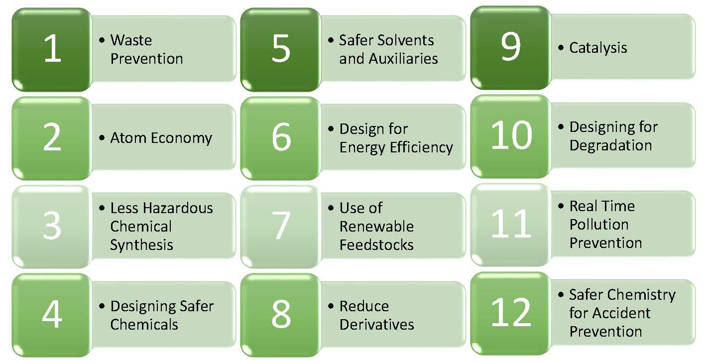
Fig. 2. Anastas and Warner’s 12 Principles of Green Chemistry6
In the quarter of a century since the birth of green chemistry, the field has moved from being considered a niche area to representing the “gold-standard” of chemical synthesis.7 However, achieving truly green synthesis is incredibly challenging, meaning that all available tools must be utilised. Flow chemistry is one such tool – an emerging approach to chemical synthesis which has much to offer green chemistry.
Flow chemistry
The glassware used to perform chemical reactions has changed very little since the early days of chemical synthesis. Traditionally, carrying out chemical reactions involves dissolving reagents into liquid solvents in round bottomed flasks, which are heated or cooled as necessary with stirring (often using a magnetic stirrer) to ensure homogeneity. Once the reaction is deemed complete usually some form of work-up process, where any remaining reactive species are quenched, is carried out. Next the desired product must be isolated from the reaction mixture via a purification process such as crystallisation or flash column chromatography before finally spectroscopic techniques such as Nuclear Magnetic Resonance (NMR), Mass spectrometry (MS) and Infrared spectroscopy (IR) can be used to confirm the identity of the product (Fig. 3A).
Flow chemistry in comparison is a continuous process. Streams of reagents are pumped through narrow diameter tubing, and reactions are carried out by meeting streams of reagents, or by passing the stream through a range of interchangeable reactors. In-line spectroscopy can be used to determine the progress of the reaction in real time, and when the reaction is complete, work-up operations can be carried out by addition of further flow reactors or streams of reagents, and in the idealised case, simply removing the solvent from the outflow results in pure product (Fig. 3B).
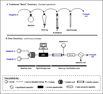
Fig. 3. A comparison of batch and flow approaches to synthesis
Green flow chemistry
Enabling Technology
While historically chemists have had a tendency to focus only on optimising the reaction with less consideration of any work-up and purification required, green chemistry calls for a more whole system approach. To be truly green, we must consider all stages of the chemical lifecycle, from the source of the chemicals used to make it, to how we isolate and confirm the identity of the chemical as well as how the chemical will be used and ultimately disposed of (or ideally reused). With work up steps integrated into the continuous flow processes, flow chemistry inherently encourages this type of thinking.
The first of Anastas and Warner’s 12 principles of green chemistry is that of waste prevention – it is far better to prevent the formation of waste in the first place, than to have to deal with it once it has been formed.6 Workup and purification steps often result in orders of magnitude more waste than the chemical reaction itself. While flow approaches can also minimise waste through enabling high yielding, rapid reactions, as we will discuss later in this article, simply by telescoping (joining together) chemical reactions with their work-up or even telescoping multiple chemical reactions, considerable reduction of the overall waste of a process can be achieved, along with significant safety improvements coming from reduced handling.8
The ability to easily include in-line spectroscopy as part of flow chemistry also fits well with green chemical principles. Rapidly advancing technology means a wide range of benchtop spectrometers are now available which can be integrated into flow systems, including UV-VIS, IR, MS and NMR (Fig. 4).9 Rather than waiting for a reaction to be complete to determine its outcome, the progress of the reaction at different points in the reaction stream can be monitored in real time. This facilitates efficient reaction optimisation, introducing the possibility of optimising the production of non-isolatable reactive intermediates8,10-11 and also allows for preventative action to be taken immediately if there is any unexpected variation in parameters (in keeping with Principle 11 which calls for real time monitoring of chemical processes to prevent pollution6).
Additionally, the real-time feedback of in-line spectroscopy has opened the door to the development of self-optimising processes,12 including utilising machine learning approaches,13 which is further enabled by the ease of automating flow processes when compared to batch processes, which often would require specialised robotics.
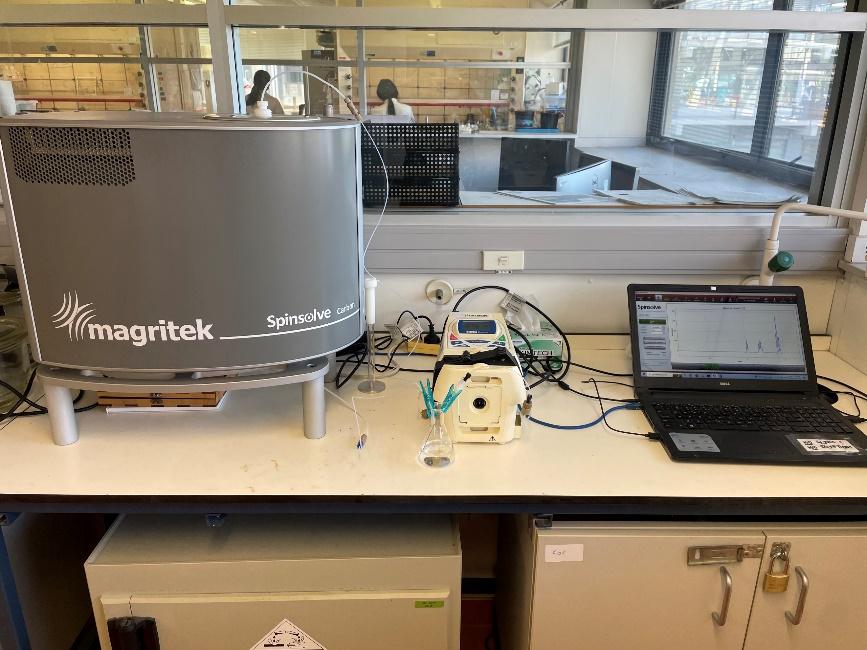
Fig. 4. A Benchtop NMR (Magritek Spinsolve Carbon) running in continuous flow mode in our lab.
Unlike batch chemistry, flow chemistry is a continuous process. This means that the reaction time is determined by the time spent by the stream in the reactor (known as the residence time) which is determined by the volume of the reactor and the flow rate of the stream according to:

While scaling up reactions in batch is notoriously challenging,14 to scale up reactions in flow the assembled flow machine is simply run for longer, with the throughput of the reaction – the amount of product produced relative to time – defining the rate at which material is produced.
Reactor coils
The simplest flow reactor is a reactor coil which consists of a coil of tubing which can be heated, cooled and/or irradiated to facilitate the desired reaction. Flow tubing can be made of a range of materials, with fluorinated polymers such as polytetrafluoroethylene (PTFE) and perfluoroalkyoxy alkanes (PFA) being widely used due to their ease of handling, excellent chemical resistance and ability to withstand temperature and pressure. Though a range of diameters of tubing can, and have, been used for flow chemistry, commonly tubing with an outside diameter (o.d.) of 1.59 mm (1/16th of an inch) and an internal diameter (i.d.) in the range of 0.5 – 1 mm is employed as this provides a good balance between surface area to volume ratio and throughput (Fig. 5). In tubing of this diameter mixing by diffusion is rapid, removing the requirement for active mixing under most circumstances.10,15
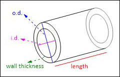
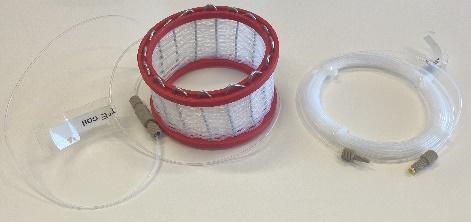
Fig. 5. Top: key dimensions used to describe flow tubing and bottom: examples of flow reactor coils.
A lot of the benefits of flow chemistry come from the increased surface area to volume ratio offered by the narrow diameter tubing when compared to the traditional chemistry glassware used in batch reactions. To demonstrate how dramatic this change is, we can approximate a round bottomed flask with a hemisphere (which is a slight oversimplification as round bottomed flasks are sometimes filled past halfway), allowing us to calculate the outside surface area to volume ratio of a series of different sized round bottomed flasks (Table 1). We can see that as we increase the volume of round bottomed flask from 5 mL to 500 mL we get a dramatic drop off of the surface area to volume ratio from 224 mm2/mL to just 0.048 mm2/mL. When heating or cooling objects we rely on heat exchange at the surface of the object so this decrease in surface area to volume ratio has significant implications when it comes to heating and cooling reaction mixtures, meaning that the reaction conditions in the flask differ as you scale up the reaction mixture. Also, as reactions are scaled up there can be a significant increase in likelihood of uncontrolled exotherms (which can result in explosions) as the cooling capacity of the reaction setup is overwhelmed.
In comparison, we can consider the reactor coil (Table 1). In the case of a commonly used diameter of flow tubing (1 mm i.d., 1.6 mm o.d.) we can see that the surface area to volume ratio is dramatically increased when we compare a 5 mL round bottomed flask (224 mm2/mL) to a 5 mL reactor coil (4000 mm2/mL), allowing almost instantaneous, uniform heating or cooling. The surface area to volume ratio is constant for a set diameter of tubing, irrespective of length (and therefore volume), though for practical reasons (long lengths of tubing required) rarely would reactor coils of over 20 mL be used.
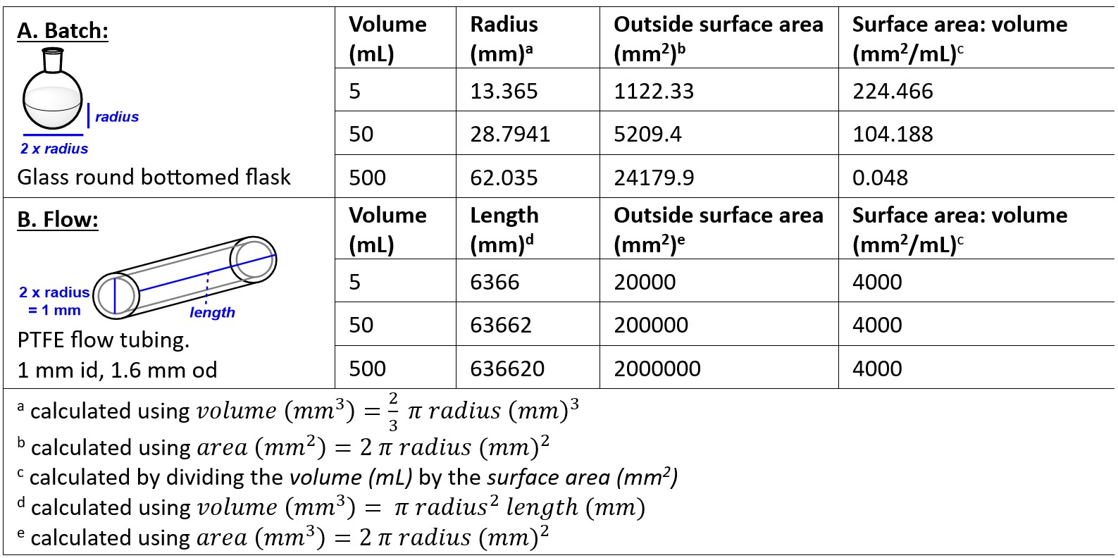
Table 1. Relationship between outside surface area and volume in round bottomed flasks and flow coil reactors.
Flow application 1: acid chloride formation and use in flow
While using acid chloride intermediates for peptide couplings has advantages in terms of high atom economy (the second principle of green chemistry6) when compared to other amide bond forming reactions, its application has been limited due to the high reactivity of the acid chloride intermediates, which makes them prone to side reaction.16
We have previously been able to exploit the efficient temperature control of flow chemistry to circumvent this limitation. Through stacking a series of coil reactors on a cooling unit (Polar Bear Plus – Cambridge Reactor Design), we were able to precool a stream of acid 4 and the acid chloride forming reagent Ghosez’s reagent (5) which were combined to successfully generate an acid chloride intermediate 6 at 0 °C, before adding a stream of pre-cooled amine 7 and allowing the stream to warm to room temperature to form a N-methylated amide 8 in flow (Fig. 6).17
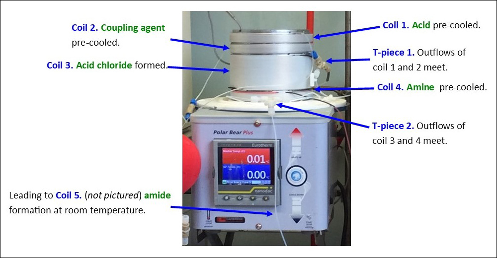

Fig. 6. Acid chloride mediated peptide coupling carried out in flow. Top: the stacked coil reactors with components identified (insulating dome removed for clarity). Bottom: a representative example of the chemical transformation being carried out.17
This approach was used to successfully synthesise a series of cyclooligomeric depsipeptides, including the natural products beauvericin (9), enniatin C (10) and bassianolide (11), in overall yields which were significantly improved from previous syntheses employing batch approaches (Fig. 7). Importantly, from a green perspective, the high reactivity of the acid chloride intermediates combined with the precise control of temperature possible allowed us to use of the coupling partners in 1:1 stoichiometry, minimising waste. While we found that these results could be replicated at small scale in batch, this was challenging, requiring the chemist to perform multiple operations. We found that when the reaction was scaled up to 0.6 mmol scale, while the yield in flow did not change, the batch yield dramatically decreased, due at least in part to the operational challenge of adding large volumes of pre-cooled solutions to each other.
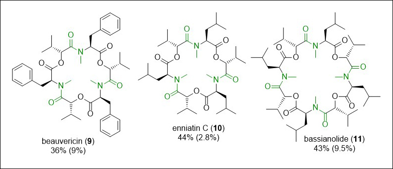
Fig. 7. Cyclooligomeric depsipeptide natural product synthesised using flow chemistry, with the key amide bonds highlighted in green. Yields for the flow integrated synthesis are shown, with comparison to previously reported literature yields (in brackets).17
Column reactors
Where in batch, insoluble solid reagents can be challenging to use, packing such reagents into refillable reactor columns, which are commercially available (Fig. 8) or can be made from readily available components,15 can lead to straightforward and highly effective reactions. Column-based reactors are packed with solid or solid-supported18 reagents, catalysts, or scavengers, and equipped with filtering frits at both ends of the column to prevent the insoluble components leaving the reactor, while the solvent stream passes freely through.10 This approach removes the requirement for a separation step to remove the solid reagent, and can improve the lifespan of immobilised reagents as the requirement for active mixing in batch can lead to rapid physical weathering which does not occur in column reactors.10

Fig. 8. An Omnifit EZ Chromatography column (Diba) which can be filled with solid reagents to form a column reactor.
The fact that catalytic reagents are superior to stoichiometric reagents in terms of green chemistry is acknowledged in Principle 9 of the 12 Principles.6 Packing heterogenous catalysts into reactor columns offers several further advantages. It can greatly improve the reusability of catalysts – particularly for reactive catalysts such as the palladium and platinum catalysts which are widely used for hydrogenation reactions but rarely can be successfully isolated from batch reactions to allow reuse.19 Additionally, while in batch reactions catalysts are usually added in the lowest possible amount to carry out the reaction reliably (e.g. 5 mol%, Fig. 9A), as only a small amount of the reaction stream is in the column at any one time, each molecule of reagent is exposed to a large excess of catalyst in a reactor column (Fig. 9B) which can lead to faster and more complete reactions.
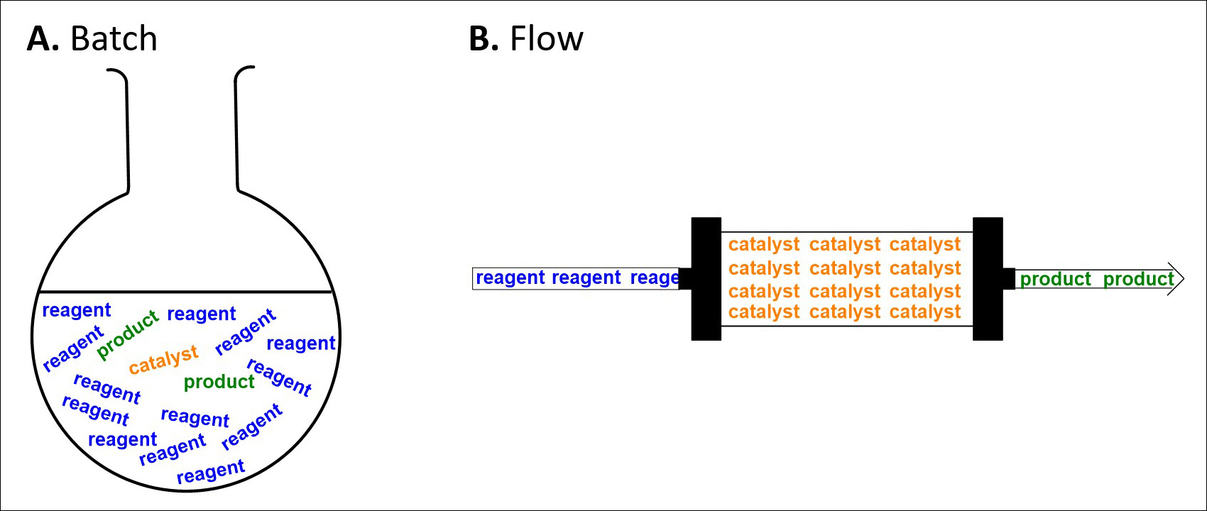
Fig. 9. A comparison of stoichiometry of heterogenous catalysis in A: Batch and B: Flow.
Flow Application 2: oxidation of oxazolines to oxazoles using manganese dioxide
When manganese(IV) dioxide (MnO2) is used in batch synthesis it has a tendency to adhere to surfaces complicating isolation of products.20 However, we found that when amorphous MnO2 is packed into a column reactor this allows its straightforward oxidation of oxazolines to oxazoles. The reaction is carried out using dimethoxyethane (DME) as the solvent, with the use of a back pressure regulator (BPR) to pressurise the reaction stream to 100 psi allowing the heating of the solvent stream to 100°C, significantly over the atmospheric boiling point of DME (85°C). This approach was successful for the oxidation of a range of oxazolines, including the double oxidation of challenging dioxazoline 12 to dioxazole 13 in 83% yield (Scheme 1).21
The successful synthesis of dioxazole 13 in flow represents a significant improvement in terms of green chemistry. The product directly from the reactor was found to be analytically pure, removing the need for wasteful purification steps (in keeping with Principle 1). Additionally, Principle 3 reminds chemists that we should carry out less hazardous synthesis where possible. Previous syntheses of 13, which was an intermediate in our total synthesis of the natural products plantazolicin A (14, Scheme 1 insert) and B, had required the use of a large excess of acutely toxic bromotrichloromethane (BrCCl3) as a reagent, and only afforded 13 in a modest 23% yield leading to a step-wise approach being used in the total synthesis. 22,23
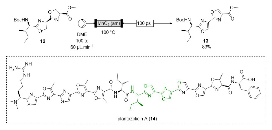
Scheme 1. Successful flow oxidation of dioxazoline 12 to dioxazole 13 and the structure of plantazolicin A (14) with the relevant structural fraction highlighted in green21–23
Improving the safety of chemical synthesis
There are two main approaches to mitigating risks, such as those represented by chemical synthesis, which are summarised by the risk equation: risk = hazard x exposure. While minimising either of these components will reduce the overall risk a process represents, the ideal situation would be to eliminate both the hazards and any potential exposure to them, which flow chemistry as an approach to synthesis is well poised to do.
We have already mentioned how the high surface area to volume ratio of flow reactors, and resulting excellent heat transfer, means that flow reactors have improved safety when carrying out exothermic reactions compared to batch reactors. Additionally, when carrying out a reaction that proceeds via a hazardous reactive intermediate in batch, usually the intermediate is first formed in bulk and then reacted, meaning that for a period of time there is a significant amount of the hazardous intermediate concentrated in the reaction vessel. The small reactor volume and continuous nature of flow chemistry means that at any one time only small amounts of such an intermediate exist, greatly diminishing the risk represented by this intermediate.10,24
In batch processes, carrying out a reaction at high pressure requires specialised equipment to mitigate the risk of explosion. In flow, simple and relatively affordable back pressure regulators (BPRs) (Fig. 10) can be attached in-line, pressuring everything upstream of them to the desired pressure.
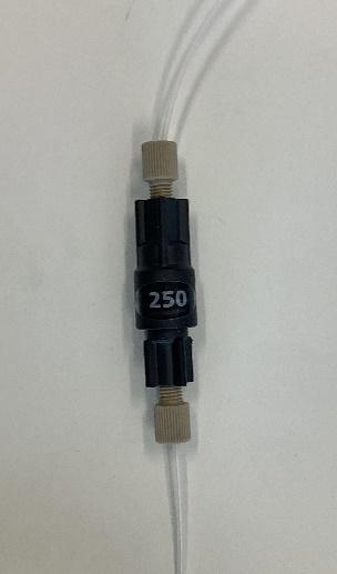
Fig. 10. A 250 psi back pressure regulator (IDEX Health and Science)
As demonstrated by Flow Application 1, the appropriate use of flow chemistry can dramatically reduce the amount of handling necessary to carry out even complicated sequences of operations, reducing the exposure of chemists to chemical hazards. A flow machine is a closed system, isolating the chemist from any hazardous chemicals being used, and the ability to include work-up/quenching steps before the reaction stream leaves the flow machine further improves the safety for operators. With increasing amounts of in-line monitoring and automation being possible as technology advances, the safety benefits flow offers only grow.8,9,11,24
Flow Application 3: safer use of carbon monoxide
Carbon monoxide (CO) gas is extremely useful synthetically due to the large range of atom efficient catalytic carbonylation reactions which are possible.25 However CO is incredibly hazardous – the odourless, colourless and tasteless gas is highly toxic and flammable, and most carbonylation reactions rely on the use of pressurised CO gas cylinders, which in themselves represent a significant hazard. Green chemistry Principle 12 - safer chemistry for accident prevention - states that the form of a substance used in a chemical process should be chosen to minimise the potential for chemical accidents.6 In keeping with this principle, we developed an approach to avoid the use of CO cylinders by generating the gas in flow and directly using the formed CO in carbonylations, made possible by a tube-in-tube reactor consisting of an outer tube made of impermeable PTFE and an inner tubing made of Teflon AF-2400, which is gas-permeable, but will not allow liquids to pass. The hydrolysis of oxalyl chloride ((COCl)2) using aqueous sodium hydroxide is carried out in the outer tubing, and then a pressure gradient established using BPRs of differing strengths forces the CO through the AF-2400 membrane and into the inner tubing where it is consumed in a chemically incompatible carbonylation reaction or aryl iodide 15 to give ethyl ester 16 (Scheme 2). CO is only generated as and when it is required, and the reactor stream is quenched as it exits the machine, minimising the risk posed by any residual CO. 26
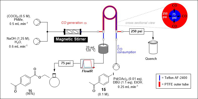
Scheme 2. Generation and use of CO using a tube-in-tube reactor in flow including a cross sectional view of the tube-in-tube reactor showing the pressure gradient responsible for diffusion of CO from the outer to the inner tube.
Challenges
Unfortunately, the advantages offered by flow chemistry come at a cost. The narrow diameter of the tubing which gives flow reactors such exceptional surface area to volume ratios also means that it can be easily blocked if a precipitate forms during a reaction. This means that solubility often becomes the key concern of a flow chemist. While green chemical principles call for minimisation of the use of solvents, as these represent waste, often the only solution to precipitation formation in flow is further dilution of the reaction stream15 or the use of specialist solutions engineered to handle slurry flow, such as continuous stirred tank reactors.27
Chemical compatibility of components coming into contact with the flow stream can also be limiting – while components can be 3D printed from readily available 3D models, the chemical resistance of the 3D printable polymers commonly used, such as polypropylene, means that such parts have a finite lifespan, especially with halogenated solvents.28
Conclusions
Despite it being over 25 years since the 12 Principles of Green Chemistry were first introduced in 1998, chemists still have a lot of work to do to make chemical synthesis sustainable.
When compared to traditional chemical synthesis, flow chemistry facilitates more efficient heating, cooling and mixing, offers improved safety, user-friendly scale-up and pressure control, while giving precise control of reaction parameters, allowing for straightforward real-time monitoring and simplifying automation.
There is still much untapped potential for flow chemistry to contribute to greener synthesis, especially in the areas of inline workup and purification, which contribute greatly to the overall waste of a process and therefore offer much scope for improvement. However, the immense promise of this area to contribute to the field of green/sustainable chemistry will ensure any effort in this area is worthwhile.
References
- Carson, R. Silent Spring, Houghton Mifflin Company, Boston, 1962.
- A town, a flood, and superfund: looking back on the Times Beach disaster nearly 40 years later, https://www.epa.gov/mo/town-flood-and-superfund-looking-back-times-beach-disaster-nearly-40-years-later, (accessed 16/02/2023).
- Broughton, E. Environmental Health, 2005, 4, 6. DOI:10.1186/1476-069X-4-6.
- Organisation for Economic Co-operation and Development Website, OECD - Sustainable Chemistry, http://www.oecd.org/chemicalsafety/risk-management/sustainable-chemistry/ (accessed 11/02/2024).
- Sheldon, R.A. ACS Sustainable Chemistry & Engineering, 2018, 6, 32–48.
- Anastas P.T.; Warner, J.C. Green Chemistry: Theory and Practise, Oxford University Press, New York, 1998.
- Erythropel, H.C.; Zimmerman, J.B.; De Winter, T.M.; Petitjean, L.; Melnikov, F.; Lam, C.H.; Lounsbury, A.W.; Mellor, K.E.; Janković, N.Z.; Tu, Q.; Pincus, L.N.; Falinski, M.M.; Shi, W.; Coish, P.; Plata, D.L.; Anastas, P.T. Green Chemistry, 2018, 20, 1929–1961.
- Ley, S.V.; Chen, Y.; Fitzpatrick, D.E.; May, O.S. Current Opinion in Green and Sustainable Chemistry, 2020, 25.
- Ley, S.V.; Fitzpatrick, D.E.; Ingham, R.J.; Myers, R.M. Angewandte Chemie - International Edition, 2015, 54, 3449–3464.
- Plutschack, M.B.; Pieber, B.; Gilmore, K.; Seeberger, P.H. Chemical Reviews, 2017, 117, 11796–11893.
- Volk, A.A.; Campbell, Z.S.; Ibrahim, Y.S.; Bennett, J.A.; Abolhasani, M. Annual Reviews of Chemistry & Biomolecular Engineering, 2022, 13, 45–72.
- Mateos, C.; Nieves-Remacha, M.J.; Rincón, J.A. Reaction Chemistry & Engineering, 2019, 4, 1536–1544.
- Karan, D.; Chen, G.; Jose, N.; Bai, J.; McDaid, P.; Lapkin, A.A. Reaction Chemistry & Engineering, 2024, Advance article, DOI:10.1039/d3re00539a.
- Lowe, D. We’re going to need a bigger flask, https://www.chemistryworld.com/opinion/were-going-to-need-a-bigger-flask/3010111.article?adredir=1 (accessed 23/02/2024).
- Britton J.; Jamison, T.F. Nature Protocols, 2017, 12, 2423–2446.
- Carpino, L.A.; Beyermann, M.; Wenschuh, H.; Bienert, M. Accounts of Chemical Research, 1996, 29, 268–274.
- Lücke, D.; Dalton, T.; Ley, S.V.; Wilson, Z.E. Chemistry - A European Journal, 2016, 22, 4206–4217.
- Ley, S.V.; Baxendale, I.R.; Bream, R.N.; Jackson, P.S.; Leach, A.G.; Longbottom, D.A.; Nesi, M.; Scott, J.S.; Storer, R.I.; Taylor, S.J. Journal of the Chemical Society Perkin 1, 2000, 3815–4195.
- Irfan, M.; Glasnov, T.N.; Kappe, C.O. ChemSusChem, 2011, 4, 300–316.
- Battilocchio, C.; Hawkins, J.M.; Ley, S.V. Organic Letters, 2014, 16, 1060–1063.
- Glöckner, S.; Tran, D.N.; Ingham, R.J.; Fenner, S.; Wilson, Z.E.; Battilocchio, C.; Ley, S.V. Organic & Biomolecular Chemistry, 2015, 13, 207–214.
- Wilson, Z.E.; Fenner, S.; Ley, S.V. Angewandte Chemie - International Edition, 2015, 54, 1284–1288.
- Fenner, S.; Wilson, Z.E.; Ley, S.V. Chemistry - A European Journal, 2016, 22, 15902–15912.
- Capaldo, L.; Wen, Z.; Noël, T. Chemical Science, 2023, 14, 4230–4247.
- Peng, J.B.; Geng, H.Q.; Wu, X.F. Chem, 2019, 5, 526–552.
- Hansen, S.V.F.; Wilson, Z.E.; Ulven, T.; Ley, S.V. Reaction Chemistry & Engineering, 2016, 1, 280–287.
- Cherkasov, N.; Adams, S.J.; Bainbridge, E.G.A.; Thornton, J.A.M. Reaction Chemistry & Engineering, 2022, 8, 266–277.
- Price, A.J.N.; Capel, A.J.; Lee, R.J.; Pradel, P.; Christie, S.D.R. Journal of Flow Chemistry, 2021, 11, 37–51.


